
Cheap Sub $25 timer prototype, but I need some help.
Electronics are the black magic voodoo child of some evil sorceress born to confuse me, and based on the comments from many people while I was searching for a way to time a race, I believe quite a few of them feel the same way I do. Looking through post after post of DIY articles with computer control boards, a spaghetti bowl of wires, and computer programming language made my head spin. Of course every single one of them says it's not that bad, but I would like to respectfully disagree. Now, I would love to just buy one and be done with it, and I would too, if I could find one that would just hook up and work. The only one I've seen that did that was the one 3DBotMaker was selling, but I missed out on those, and apparently there aren't any more. So, while contemplating throwing away a big chunk of money on a pile of electronics that I knew I'd never be able to put together and make work, a thought hit me. Why not make it mechanical?
So, here was the thought. Instead of using light beams to trigger the timers, why not just use a mechanical switch? So, I bought a bag of momentary Switches $7, a spool of wire $7.50, and a cheap stopwatch $8. And then I set out for a few frustrating evenings of failure.
1. Wire up the stopwatch - This wasn't that big of a deal. There are articles on here about a DIY timer that shows you how to wire up the stopwatch. All I did was pull the housing apart, and solder a wire to each side of the switch. Then, drill a hold in the casing so you have a place to run the wires through.

2. Make the watch start - Again, this was very easy. I'll tie the two wires to a switch and mount it to the track so that the starting gate activates the switch.

3.Make the watch stop - Aha! So here is where I ran into the problem. The switches are too stiff, and their throw is too long. I tried various ways of mounting the switch, under the track, through the track, on the sidewall of the track, and none of it worked. The cars don’t have enough weight to trip the switches, so mounting underneath is a no go. I tried it with just the switch, then with a hinged ramp the car would roll on to try and give it some leverage against the switch, but there just isn’t enough weight in the cars to do it. Next I tried mounting the switch on the side of the track, hoping the car’s momentum would help it trip the switch, but there is too much throw in the switch and it’s too stiff still. Some cars would be wide enough to trip it, but others wouldn't, and none of them really had the power to do it anyways. I tried making my own easier to move switchs, but that was an epic fail, and that led me to my current iteration.
 I made a swinging gate, here out of a popsicle stick and a duct tape hinge. I did have to bend the arm on the switch to get the movement correct. The added length of movement from the popsicle stick makes the switch activate with any car, and there is a leverage advantage that makes it easier to push the switch, and it actually works, but not perfectly, and so far only in prototyped practice. Because of the hinged gate, cars of different shapes will have slight advantages over others. I can actually live with that, but the switch is still fairly hard to push. The cars do trip it, but they have to be going at a decent speed, and some of my cars just manage to crawl across the line. So, this is where I need the help of the electronic wizards. Is there a better switch or a better way? Heck if you are a non wizard, can you think of a better way to activate the switch? I think this would be great way for all of us non-electronically minded people to be able to cheaply and easily time races, if I can just get it to work.
Discussion
If it used light sensors like 3Dbotmakers then it would be great. I made my diy finish like that way and it works great and has made me want to try a stopwatch/timer setup using sensors. I'm terribly stupid when it comes to wiring etc and my brain still hurts trying to get the finish line to work properly so itll be a while before I attempt it but would like to try some day. Good luck!
Matt
- I agree that sensor are the way to go, but every one I saw required a circuit and computer programming, which were the two main things I was trying to avoid. If there's some way to wire up the light sensors without a control circuit, let me know. I'd be glad to try it. — 213Racing
- No clue on that. The Arduino board I bought for my finish line was $15 and the software to run it and code to make it work were free and provided by the DIY instructions I followed. — Mattman213
- You can avoid the computer programming but not the circuit if you're using any sort of sensor. A purely mechanical solution is what the old HW sets come with and that's all springs and stuff. You're either solutioning with electrical engineering or mechanical engineering. Pick your poison. — redlinederby
I did like the idea Diecast64 used in their finish line build in still using sensors, but putting them in the structure at the top, and then using the flipper to break the beam rather than the car.
But if you're trying to avoid sensors all together then it's not what you want, obviously.
- I thought about using the flippers to press the switches. I could get some good mechanical advantage that way, but the paddles would come to a complete stop when the switch bottoms out, and I was afraid of breaking things. I might try it next though if I can't come up with another solution. — 213Racing
I like your idea.You may want to check out these micro switches.I think I got these off of e-bay several years back.Built a Skeeball alley with them. .These have a very light touch,nothing like these ones you are trying out.I've even used them on a home made Nerf target,very little contact needed.
I may copy your Idea.Did I say I like your idea? ;>)

- Ooo cool...like hair trigger switch. Much easier than the roller switches — redlinederby
- I like this idea, and I might try it, but I'm still trying alternatives. I don't like the fact that they seem to be old stock, which means if anyone else wants to try and build it they might not be able to find them. I did try to find a source for new switches like that but couldn't. — 213Racing
Here is a link to some just like mine.Hope posting this link is OK.If not please remove.You may be able to find them cheaper.This is one of the 1st ones we ran across.
213, I cant help you with your current project, however I can tell you I was in the exact same situation you are in. I wanted a timer, but had absolutely ZERO experience with the electronics side and I had never even seen an arduino before. But, I purchased all the parts (arduino based), and built it one step at a time...and trust me its all laid out for you step by step. And ended up with a great timer. I even built a second one. I think what might happen with your current project is it will just frustrate you eventually leading to the "ahhh the heck with it" attitude. You have probably already seen the website...but I used dfgtec.com with EXCELLENT results. If you have any questions regarding the timer, I will try my best to answer them. I should also note that even though I dont have any electronics experience, I can solder fairly well from my old RC car racing days...and there is a bit of soldering with this project but it's all just small stuff nothing major. Hope this helps.
- I can second this. I used the dfgtec.com to make a great timer, (it can even be hooked up to a laptop to record results with free software) even though I had previously had zero experience of electronics, Arduino or circuitry. I own't deny there were a couple of head scratching moments along the way, but I just took it one step at a time and I got there. I'll say again, I had ZERO experience of circuits, electronics or Arduino/computer programming before this build. It really was quite an eye opening experience for me. — TuxMcBea
I think this shows why light sensors are much better in this application than mechanical switches. It doesn't really matter what shape the car is. This video walks you through all the steps and the components involved are pretty cheap.
- Maybe you should do a small run of finish lines (nontimers) for the RLD family...just saying ;) — Go_Time
- Whatever happened to the prototype you came up with 3D. The one that Aaron talked to you about with the track going through the finish line and the timer incorporated into it. One with the starting gate and timer as a package deal would be sweet. — 41-14
I like the idea of the recessed sensor in the track and the wheels are spinning on how it could be done with orange track. That being said, while I'm not looking for a timer is there a way to use these sensors as a finish line? Can they be connected to a small light that would sit to the outside of the track, in line with the sensor? The first car crossing over the sensor triggers the light to indicate the winner. Just have to figure out how to shut down the light when the other car crosses the sensor. No need for paddles, wiring from the start gate, or an overhead tower.
It could be the upside down version of 3Dbotmaker's finish line.
I have no doubt that the light sensors are the best way to go, and I would love to go that route, but when I was stating that electronics are black magic, I wasn't joking. In the Make: article, he just pops up a picture of a wiring diagram and is like here you go. That doesn't work for me. I tried reading the article too and it makes no sense when it gets to the circuit. I was going to order the parts and give it a go, but I don't even know what parts to order, and the article doesn't just list them for some reason. Does anyone have a list of components to buy?
I've read over the stuff on dfgtec.com four times now and go crosseyed about halfway through. I like the fact that they sell you the parts, but those parts aren't the same as the ones in the Make: article, and I have no idea if I could make any of it work. I get very lost and can't follow what on earth they are talking about.
I've tried the Arduino's before because everything seems to use them, but my projects never work, and no one can ever tell me what the problem is (besides me). I have genuinely given them a go, I'm not just saying I can't without past experience.
I promise I'm not as stupid as I sound. I can do almost anything I've ever tried except sing and wire electronics. If someone could show me the parts I need and how to wire it, I have no problem soldering, constructing, fabricating, or machining whatever I need to make it work. I just can't wire it. The mechanical switches were an attempt to get around making the circuits because no one lays out the pieces, steps, and information in a way I can understand. I really would love to have the light sensors, or an infrared/laser sensor so they could be mounted sideways the way 1:1 cars do it, but I'm completely lost here.
I just watched the video again and noticed he really doesn't explain much about his circuit. Hope this helps a little.
- Bless you sir. I'm going to give it a shot, even though I'm still not sure I understand the wiring diagram, this should be enough to get me started. — 213Racing
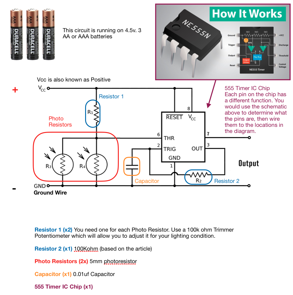
- After looking at it, I'm not sure where the second trimmer resistor goes? — 213Racing
- Man...that makes it so much more clear. Thanks! — Mattman213
- He should have drawn a resistor going to both trimmers. Pretty much you want to be able to adjust the "positive" voltage going to each of the trimmers. — 3DBotMaker
- Also just a disclaimer. I've never made this exact set up or worked with a 555timer, but it looks like it should work. — 3DBotMaker
- Get a breadboard and some breadboard jumper wires and then just connect the different points on the diagram. If you make a mistake you can easily move the wires around. — 3DBotMaker
- I order them with the other components this morning. I figured it was in my best interest to be able to easily rewire things. When the stuff gets here I'll post an update whether I can make it work or not. — 213Racing
- Correction to what I wrote above: there should be a resistor/trimmer going to each of the photo resistors. — 3DBotMaker
Everything came in except for the jumper wires, so I just made my own. Of course, I couldn't get it to work. Picture #1 is wired up the way I think 3dBotMaker was talking about with the dual trimmers, but I couldn't get the left most photoresistor to do anything. The right one works Okayish. It was a little hit or miss, but it would work. I tried replacing everything that was specific to the left photoresistor, including the trimmer, wires, and photoresistor one at a time with no change. I also tried adjusting the photoresistor to all different settings, and even held a flashlight over it to make sure it had plenty of light. I did check the voltage and both photoresistors were getting the same voltage with the same settings on the trimmer.
Then I tried just wirining it up like the Make: article said to do (picture 2) with only one trimmer, and it was still the same. I am of course now completely lost and have no idea why it won't work.

To go along with this, the stopwatch I bought specifically for the timer had no soldered connections anywhere in it, and when I tried to solder to them, the solder just slid right off and wouldn't stick? I just used the old crappy one for the testing.
- Im too dumb to help, but keep at it. My finish line did NOT want to work and I couldnt get it to save my life. Then I was walking it towards the garage to look into it deeper with it plugged in and it started blinking. Come to find out I needed a different light source to make it work and after some fiddling I ended up getting it right. Keep at it and hopefully itll come around. — Mattman213
A quick update. I failed at getting the light sensors to work properly. I tried reconfiguring the setup, but I have no idea what I'm doing and could never get more than one sensor to work at a time, so I decided to just combine the two ideas. I used the mechanical switch on the starting line to start the timer and the light sensor to stop it as cars cross the finish, and it all works fairly well this way. The trimmer was a great idea because I had to fiddle with it for a long time before I got the sensitivity right for the photoresistor to work.
I also got a new stopwatch from Walmart that actually had soldered connections and was much easier to attach the wires to. It's all a mess of wires right now, but this was as far as I got this weekend.
I'm going with this because it works and I'm tired of messing with it and would rather get back to the cars, but I am a little disappointed. I failed at both goals I set out to meet. The price is now way over $25. The pieces themselves were cheap, but I have no place to buy them locally, so I had to buy multipacks of everything from Amazon, and seeing as I had to do most of it 3 times anyway, the price jumped up pretty quickly. It's still way cheaper than buying a kit online, but not as thrifty as I wanted. I also had to build a circuit to make it work which I direly wanted to avoid.
Hmmm...probably not the best idea, but what if you had the switch behind a bumper wall at the end of the finish? So like the cars bump into the end of the track and that pushes in the switch...?? That way the full force of the car is used, maybe...I dunno.
But I'm with you in the black magic of electronics. Schematics are like sand script to me...yes it's a "simple" circuit but I wouldn't know a simple circuit from a complex circuit, so all of it is nuts.
I wish I had more time to futz around with finish line stuff. Now that I have a 3D printer, I feel like I could even print some supporting pieces/parts and maybe come up with some sort of kit. It's a bummer that 3DBM quite producing his finish line, but even if someone just make a DIY kit that included all the parts and I had to assemble it, I'd consider that a huge win and open my wallet for sure. I need a Lego-style solution...give me a bag of parts and some directions.